pixel pressure pad
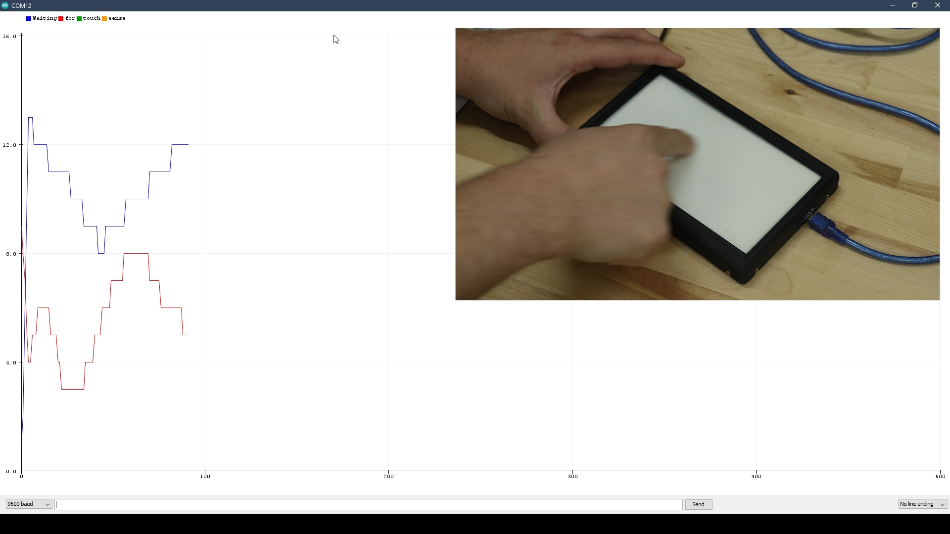

I made a device that I'm calling the pixel pressure pad. I used an array of RGB LEDs behind a resistive touch sensor. An Arduino Nano reads the touch inputs and controls the LEDs based on where I place my finger.
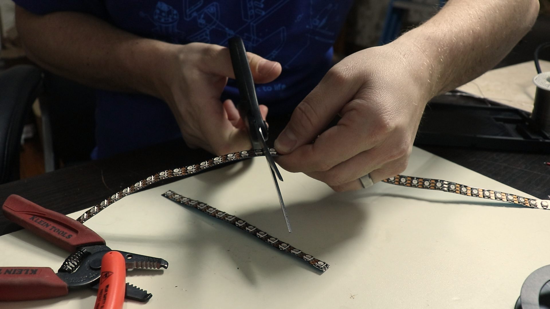
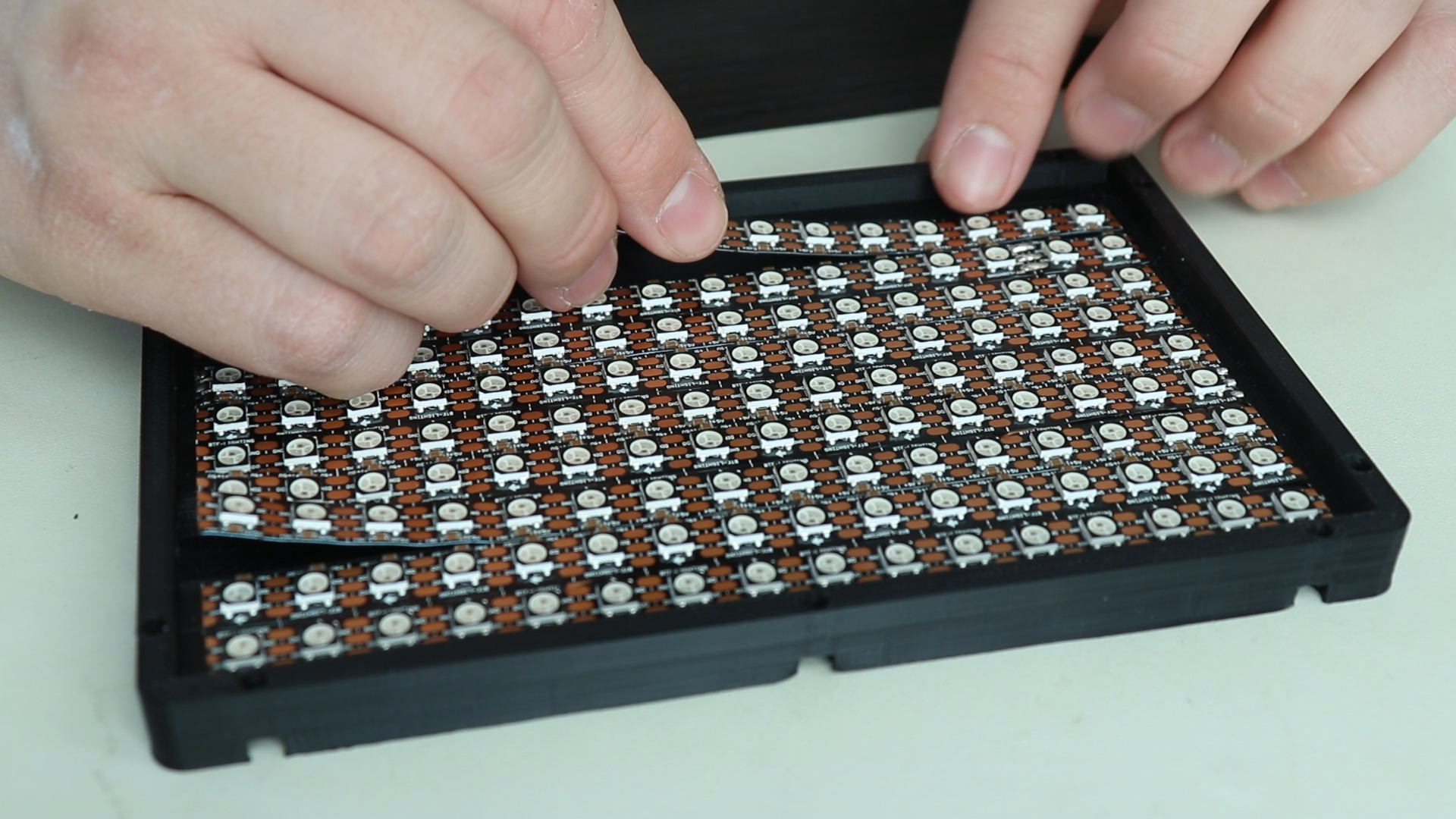
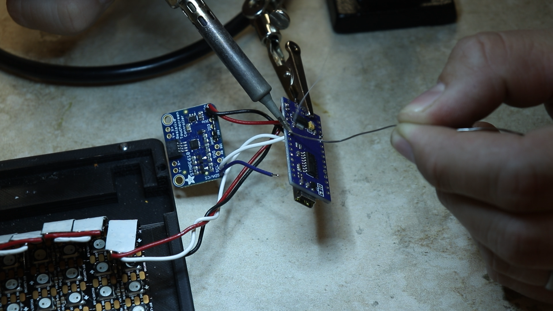
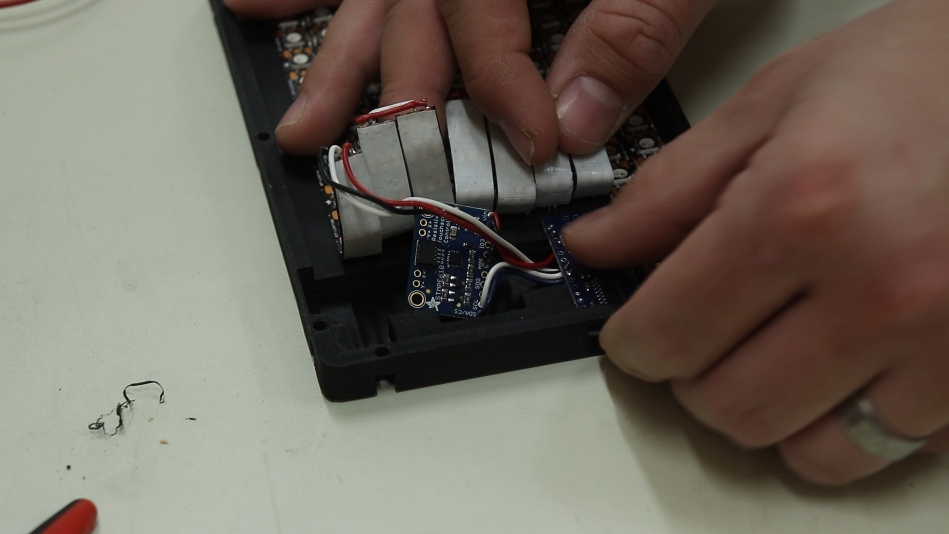
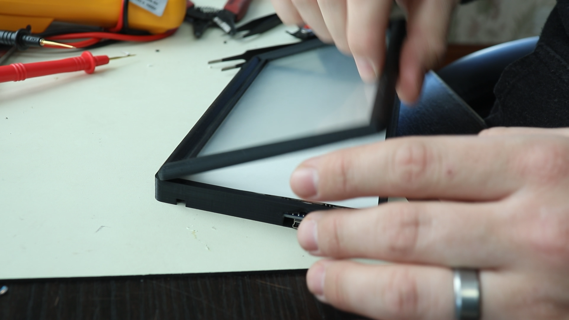
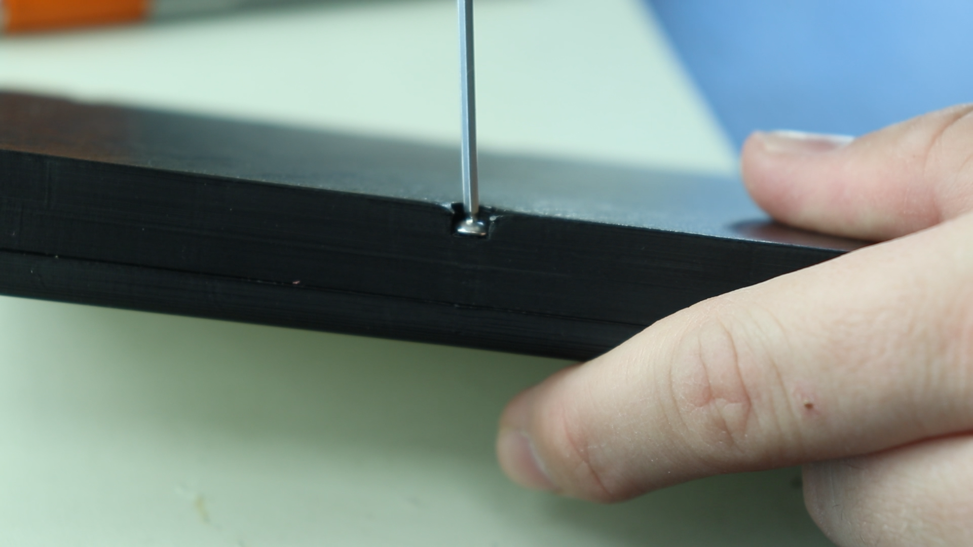
First I designed and 3D printed an enclosure to fit the resistive touch screen. I made sure to include slots for the Arduino Nano and touch controller boards. I started out by using a small amount of CA glue (super glue) to adhere the touch screen to the top portion of the enclosure. When you use too much glue the fumes will damage the clear touch screen reducing visibility. Don’t ask me how I know that! Next I cut the LED strips into 9 equal lengths each with 16 LEDs on each strip. I removed the adhesive backing and placed them inside the 3D printed enclosure making sure to alternate the direction in a serpentine pattern. The LED strips have 3 signals; 5V, GND, and data. I cut some 24AWG wire to connect each link to the next using different color wire for each signal to help keep them straight. Next I soldered the 3 signals to the Arduino Nano board. I connected the 5V signal to the VIN pin on the Arduino Nano so that I could take advantage of the current source of the power supply. These LEDs use quite a bit of current and the on board voltage regulator that supplies the 5V pins on the Arduino cannot source enough current. The GND signal wire is connected to the GND pin, and the data signal is connected to digital pin 2. Next I connected the power pins of the touch controller to 5V and GND on the Arduino. The touch controller has a “mode” pin that needs to be connected to GND to use the I2C bus of the chip. Next I connected the I2C wires from the touch controller to the Arduino pins A4(data) and A5(clock). With all the wiring done I connected the touch screen into the touch screen controller using the flat ribbon cable being careful not to damage the cable. I wanted to diffuse the LED lights, so I cut some thick white cardstock paper the same size as the touch screen. I inserted this between the LEDs and the touch screen and I closed everything inside and secured the bottom part of the enclosures to the top using M3 screws. Now it was time to write some code. I used the Adafruit library for the touch screen controller to read the touch inputs. I used FastLED to write the LED animations based on the touch screen inputs. There are a lot of potential applications you could write for the versatile platform.