Wood Lathe Digital Readout
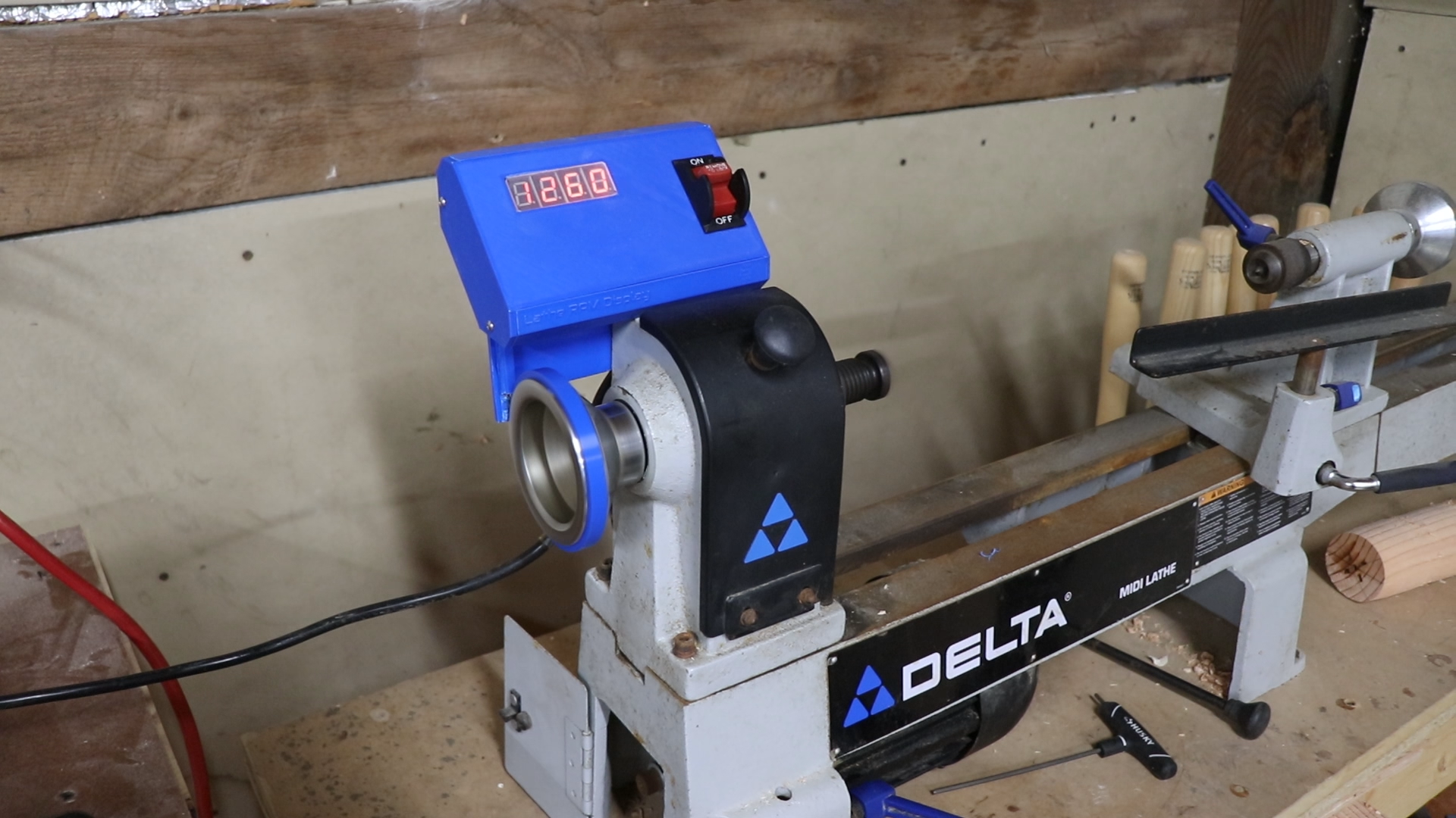
Materials:
Hall Effect Sensors: Amazon (20pk) Amazon (inductive switch)
Arduino Nano: Amazon (3pk)
Seven Segment Display Common Cathode: Amazon (10pk Red) Amazon (4pk Blue)
N-Channel Mosfets: Amazon (50pk)
Resistor Assortment Pack: Amazon (1280 pieces) Amazon (3350 pieces)
Neodymium Magnets: Amazon (200pk)
5V DC Transformer Module: Amazon (2pk)
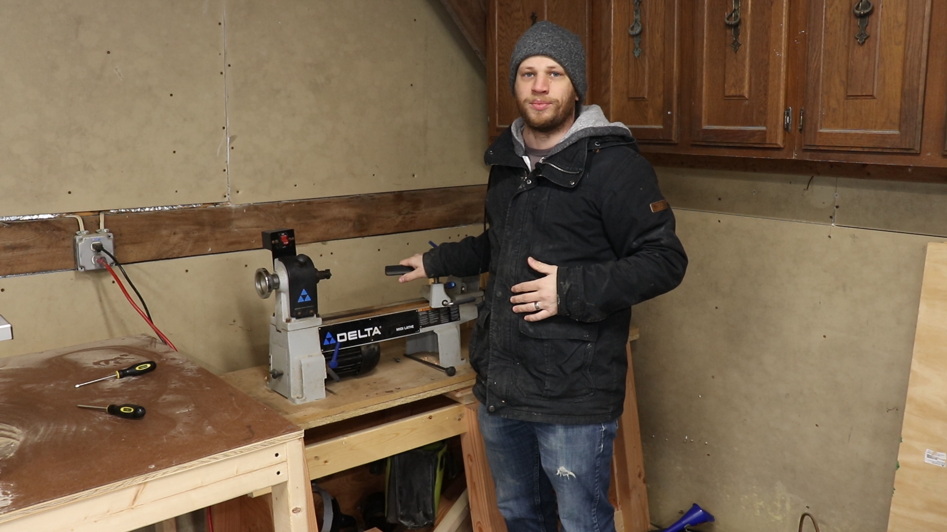
I bought a wood lathe a few months ago and I thought it would be fun to make my own digital readout. A digital readout is simply an electronic display that shows you the spindle speed of a lathe. I’m not very knowledgeable when it comes to wood lathes, but out of the ones I found not very many had a DRO for the spindle RPM.
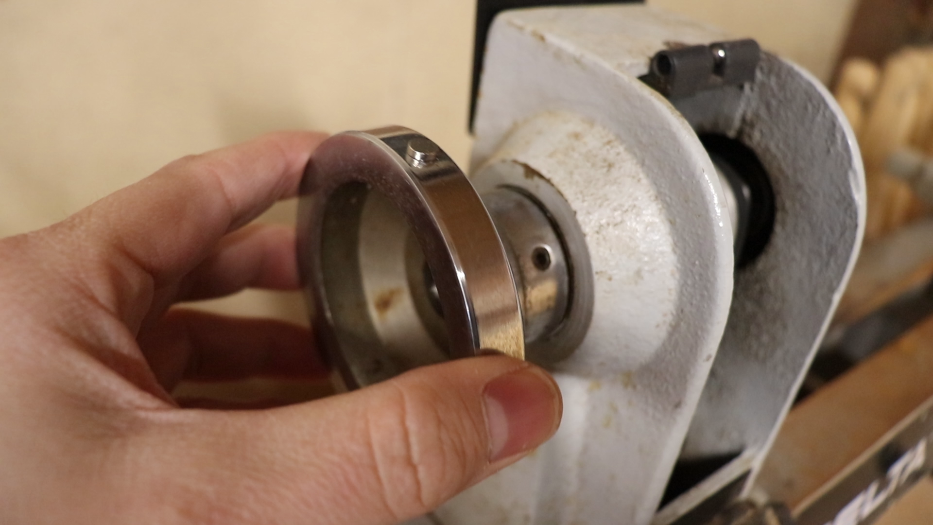
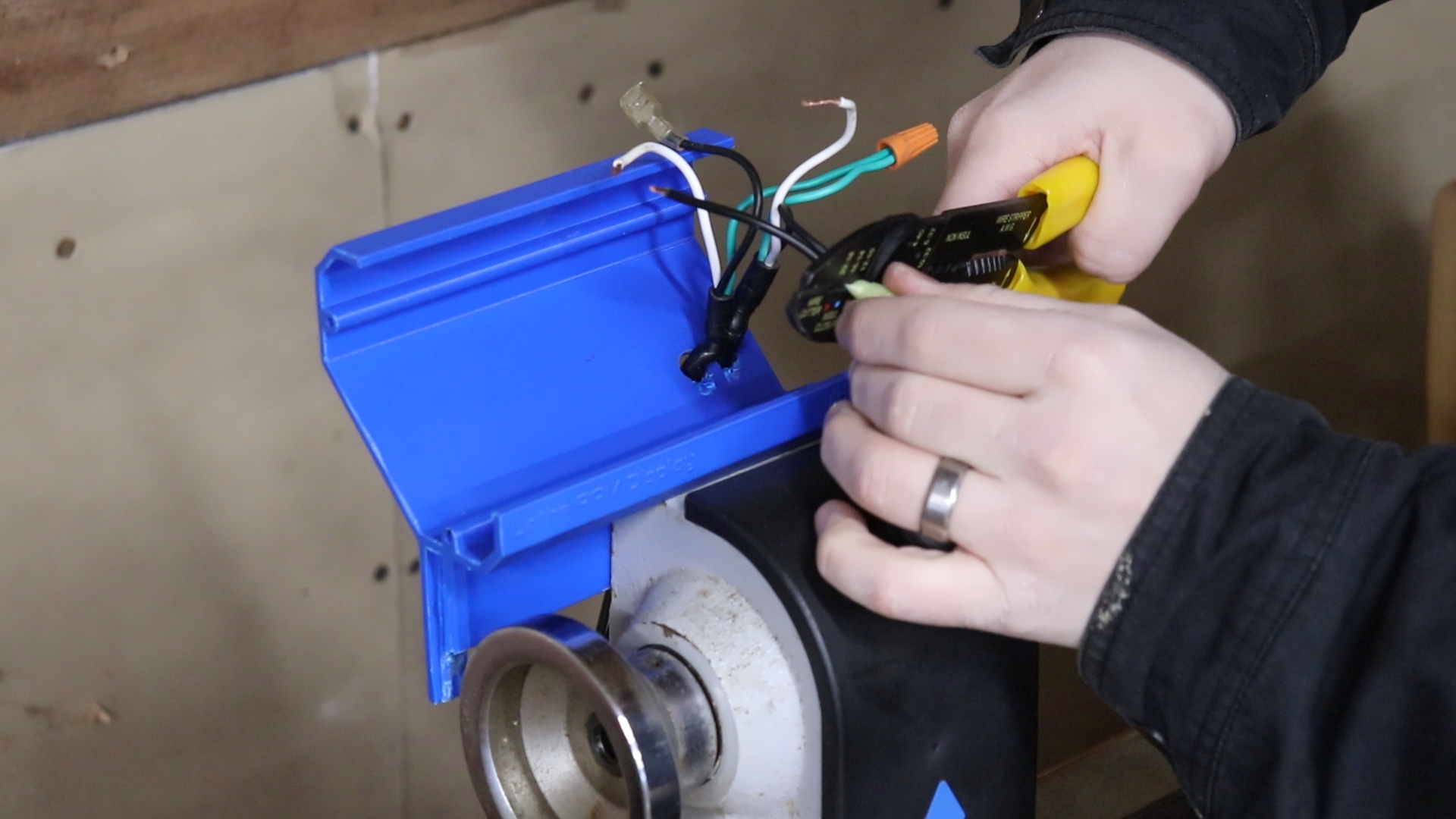
I started brainstorming different ways to measure the rotation of the spindle and I decided that a hall effect sensor would be the best way to go. A hall effect sensor is really just a device that can measure the presence of a magnetic field. My plan was to place a neodymium magnet on the rotating spindle then use a hall effect sensor to measure that magnetic field every time it passed by. I figured I could use an Arduino board to read the sensor, count the pulses, and calculate the RPM of the spindle. To display the RPM I wanted to use some seven segment displays. My lathe already had a power cord coming into a plastic box with a power switch. I wanted to include that power cord and switch in my design so I wouldn’t have to use a separate power supply for my electronics.
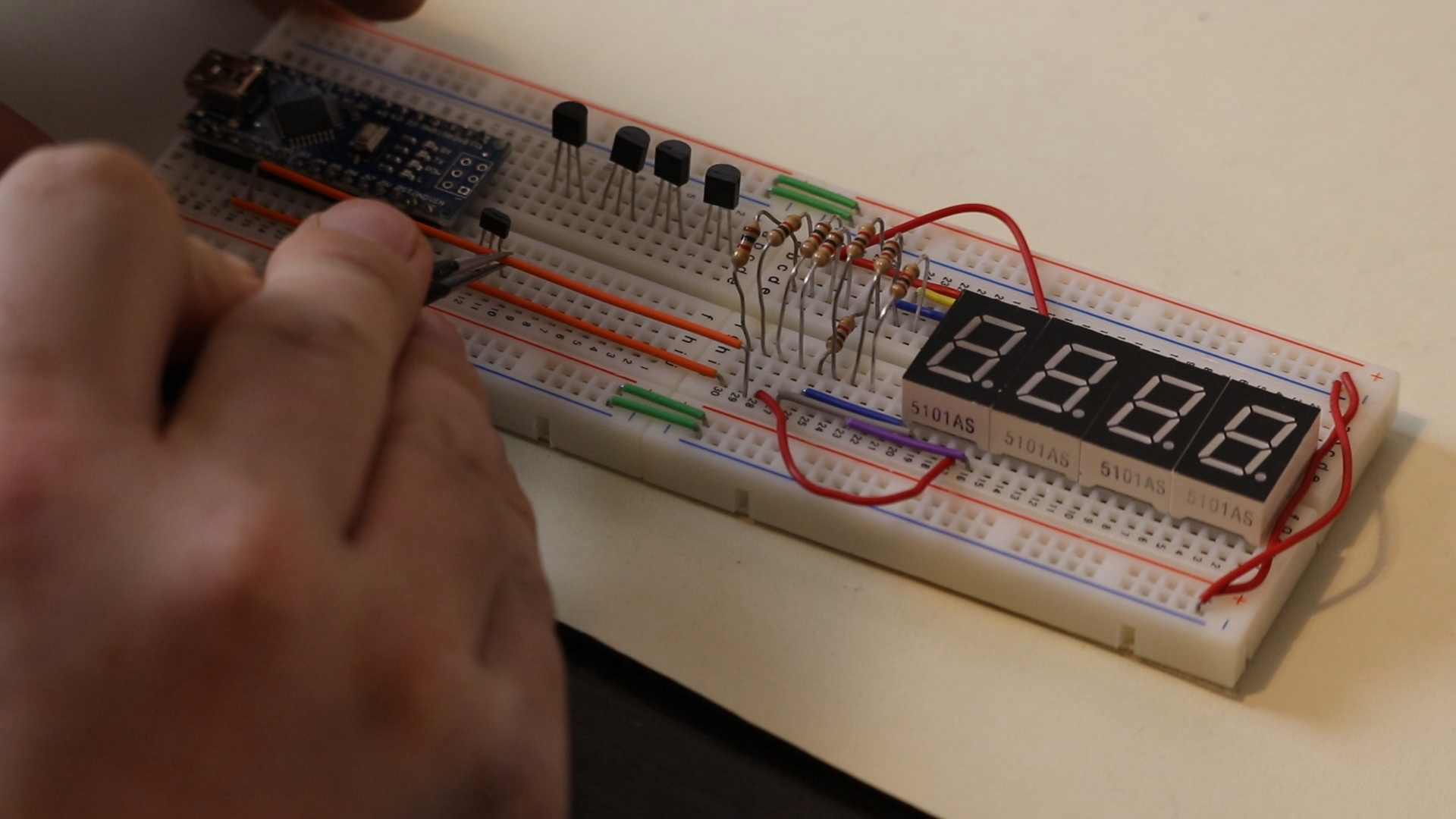
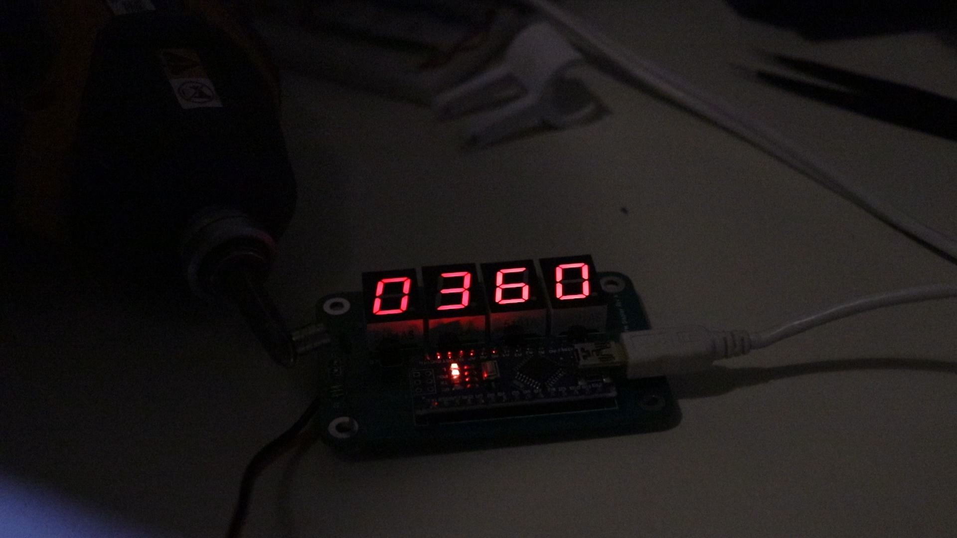
I started by rummaging through my stash of electronics to see what I already had. As luck would have it (or my hoarder tendencies, not sure which) I already had everything I needed to build a prototype on my bench. I used a breadboard and jumper wires to connect everything together. The seven segment displays have a common cathode which needed to be driven low using an Arduino pin. When all the LEDs are lit (for example when displaying the number 8) all the current will flow through that one pin. Since Arduino pins can only source or sink about 40mA of current I knew I needed to use a MOSFET transistor for each digit to do the heavy lifting. I wrote some test code on the Arduino that displayed numbers that incremented every second.
The hall effect sensor gets connected to 5V and GND and outputs a low pulse every time a magnetic field is present. To read these pulses you could have the Arduino read the signal on an input pin. However the code to display numbers on the seven segment displays keeps the processor pretty busy and it’s very likely it would miss a low pulse if it wasn’t looking for it at the right time. That’s why in this scenario you would want to use an interrupt pin. When a signal is applied to an interrupt pin it doesn’t matter what the Arduino currently doing. It stops what it’s doing and executes a little piece of code called an “interrupt service routine”. This way the Arduino doesn’t have to babysit the hall effect sensor, it can go about its business displaying numbers and what not. When the hall effect sensor pulls the interrupt pin low, it’s letting the Arduino know it’s time to run the interrupt service routine. I wrote some more code to read the hall effect sensor and calculate an RPM value to show on the seven segment displays.
When I was happy with the prototype, I created a schematic using KiCad. Then I took that schematic and turned it into a printed circuit board (PCB) design. I sent the design files off to a manufacturer and received my PCBs in a couple weeks.
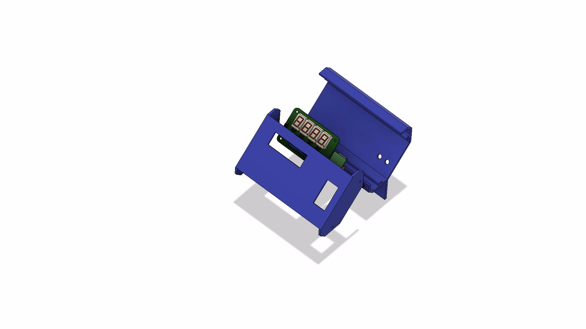
While I was waiting for the PCB to come in the mail I started working on designing a 3D printed enclosure. I used Fusion 360 to design the enclosure. It needed to fit the PCB with the seven segment displays, as well as the power supply, and the power switch. I have a 3D printer that I’ve been using for a couple of years and it’s worked great. I made a video about it if you want to check it out. While moving to Vermont last year one of the structural pieces broke on the frame. I decided to take my chances and went ahead and used it to print the enclosure. The print time was estimated at 14 hours so it was definitely one of my longer prints. My first attempt failed after 4 hours, but it was my fault. I made a mistake on the heated bed temperature. The second attempt went all night long and looked great up until hour 12 when something misaligned and I ended up with a completely unusable part. I did try out a cool new time lapse method for 3D prints and I captured most of the print. I was really frustrated at this point and I broke down and bought a new 3D printer. This new printer did a wonderful job with the print and I think it will work more reliably than my previous printer.
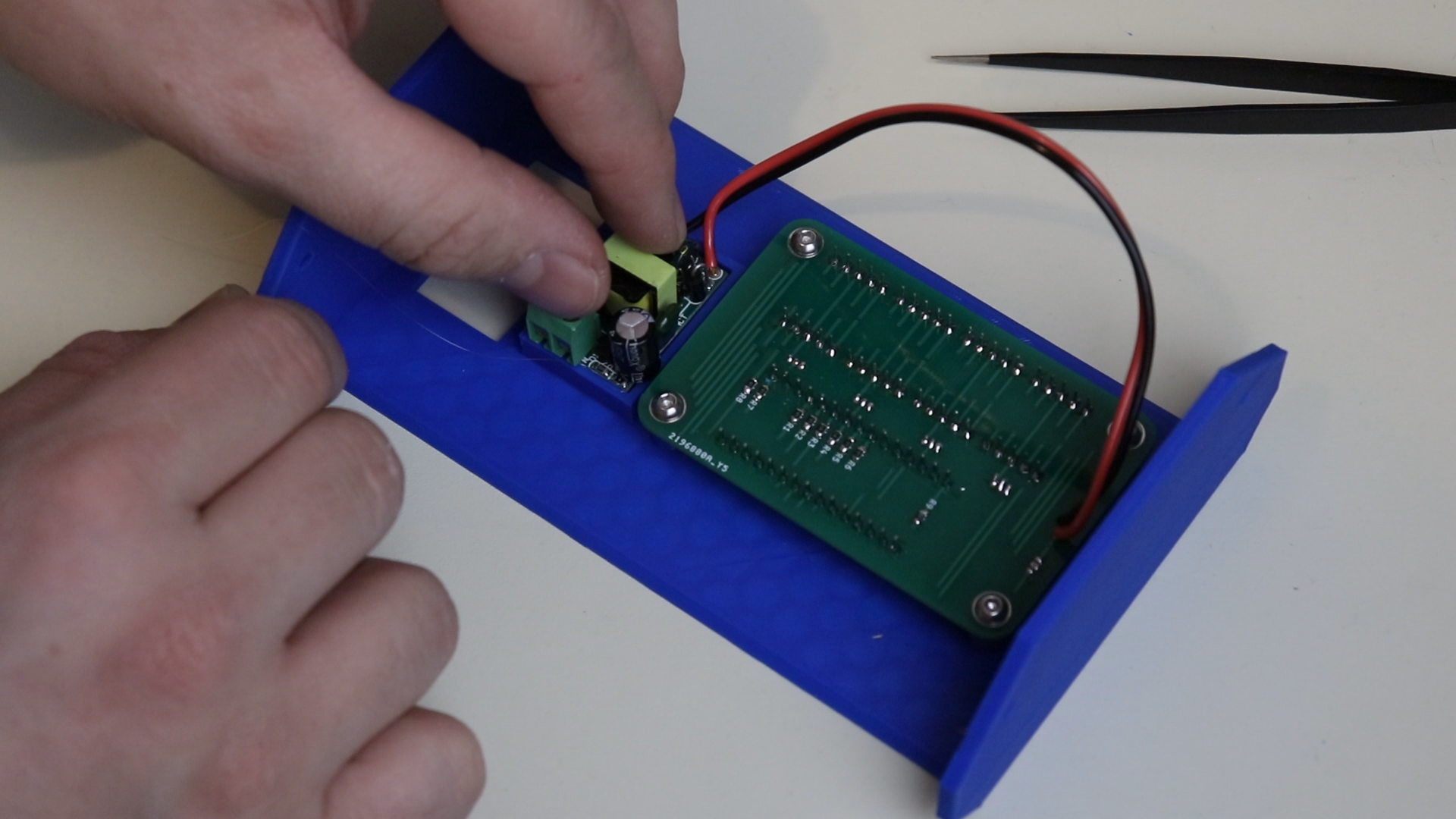
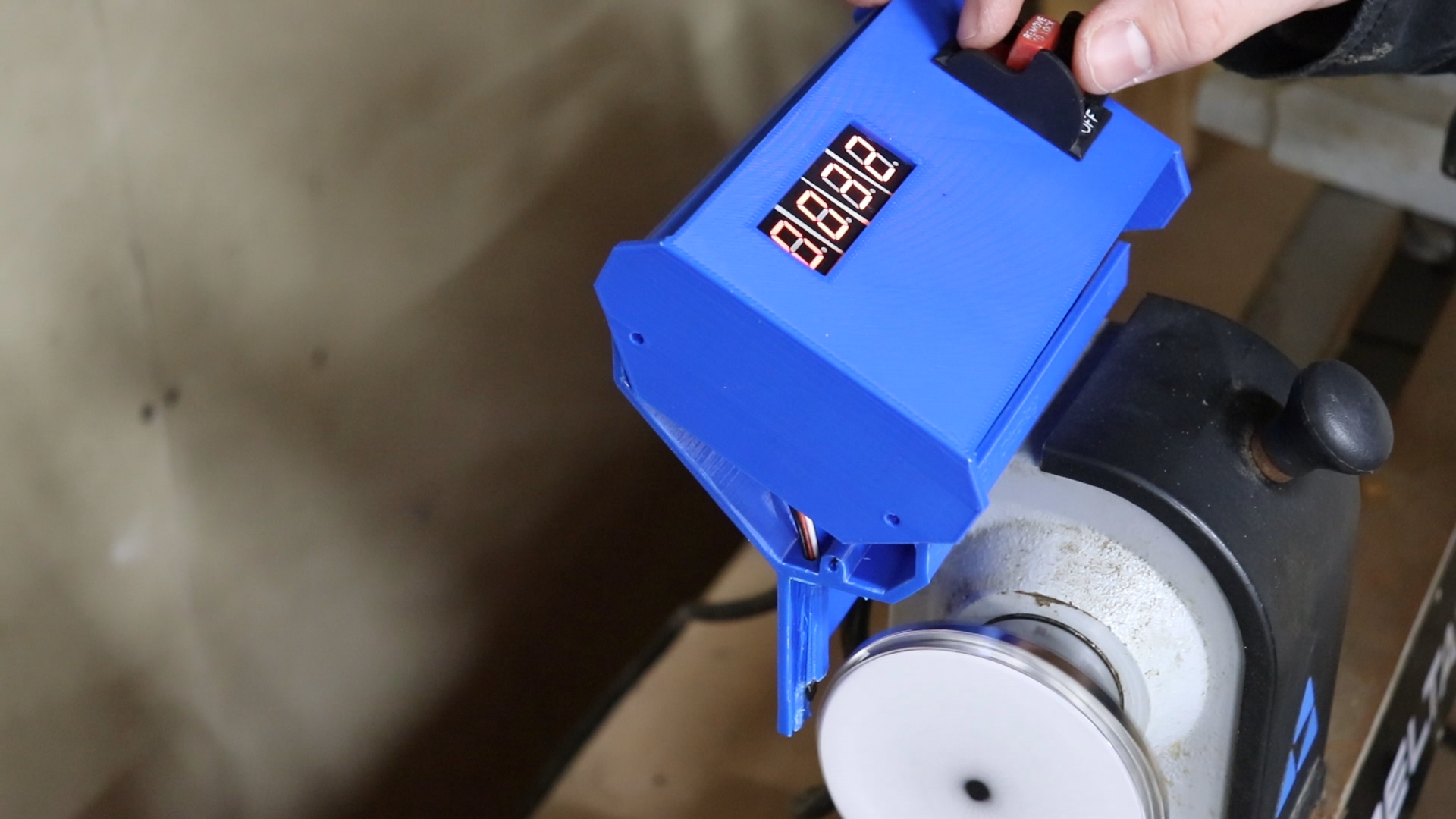
When my PCBs arrived in the mail I took components one by one from my breadboard prototype and soldered them to the PCB. When I was finished I started assembling everything into the 3D printed enclosure. At that point I was ready to install my digital readout on my lathe. I took everything out to my garage and got it installed. When I fired it up I was getting some weird readings that didn’t quite look right. I brought my oscilloscope out to the garage and connected a probe to the hall effect sensor output. It seemed like every time the magnet passed the sensor I was getting two low pulses. I also wasn’t getting very high resolution on my readings. So I added some more magnets to the spindle and fixed the code so it was expecting two pulses and everything started working! I closed it all up and finished the project by putting a piece of sanded acrylic to act as an LED diffuser.
